-
Notifications
You must be signed in to change notification settings - Fork 6
z Frame (archived Winter 2013)
nxrlab edited this page Apr 5, 2013
·
1 revision
- Heat sink motor to extend continuous region.
- motor specs 133 rpm, 10 Nm (safety factor 1.5)
- mass (m) < 5 lbs max per link
- link length (L): 12'' < L < 18''
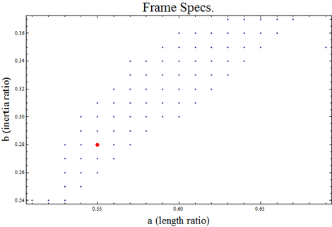
- nominal parameters: a = 0.55, b = 0.28 (a * L is the distance from the elbow joint to the center of mass and b = I/(m*L^2), where I is moment of inertia about center of mass); other options are shown in the plot below. The red dot is the nominal point.
- magnet tangential holding force > 40 lbf (note that manufacturers list normal holding force)
- batteries (x2): (see spreadsheet)

- Motor Selection/Gearing
- Electromagnet Selection - 40 lbf tangential force on a .125" thick steel sheet
- Develop way to pass power to magnet thru rotation
- Design/CAD/CAM links
- Magnets/bearings selected/ordered
- CAD of magnet/slipring assembly
- Motor selected/ordered
- Gearing selected (and ordered, if applicable)
- Decide on best material for frame
- Rough layout of component positioning within links
- Design pivot point (how gears are packaged, how the links are connected, bearing selection, etc)
- Magnet encoder selected/ordered/added to magnet assembly
- Gather information from other groups about all components that need to be packaged (sensors, PCBs, batteries, etc)
- CAD - 1st iteration of the frame, with rough placement of all components
- Finalize CAD model of frame design
- Incorporate attachment methods for all components
- CAD/material selection for an required covers
- Order frame material
- Detail drawings of all components we are making
- CAM/G-code for both links
- CAM/G-code (if applicable) for magnet assembly
- CAM/G-code (if applicable) for motor/gear mount
- If time allows and machines are available, begin machining frame and/or smaller components