-
Notifications
You must be signed in to change notification settings - Fork 25
Getting Started with MyoBridge Firmware

This section describes how to use the MyoBridge Firmware with a HM-11 module. For other devices using a TI CC2541 / CC2540 BLE SoC, pin layouts, etc will be different, buf the general steps would be similar. If you are not using an HM-11 BLE Module, you might have to adjust the MyoBridge Firmware to your pin setup.
Things you need:
- HM-11 or other compatible BLE module
- CC Debugger or https://github.com/RedBearLab/CCLoader (Used by eric_castro https://developer.thalmic.com/forums/topic/2707/?page=1)
- Soldering equipment, breadbord is probably useful.
This image shows the necessary pins you have to have access to in order to use the module:

Also refer to the HM-11 Datasheet or nickswalkers page showing the HM-10 pinout (https://github.com/nickswalker/ble-dev-kit/wiki/HM-10-Pinout).
Connect the soldered wires to the cc debugger as discribed in the [CC Debugger User's Guide] (http://www.ti.com/lit/ug/swru197h/swru197h.pdf) on page 8. Here is an image showing this for the HM-10 (image from http://hackersome.com/p/rampadc/cc2540-hidKbdM ):

After a reset the CC Debugger LED should be green. Your can now proceed flashing the firmware.
For flashing the firmware your need the [SmartRF Flash Programmer] (http://www.ti.com/tool/flash-programmer). Be sure to use Version 1! Follow the instructions on how to use SmartRF Flash Programmer here. Use the MyoBridge_<your_chip>.hex file.
If there is no such file for your specific chip or you want to modify the firmware, you have to use [IAR Embedded Workbench for 8051.] (http://supp.iar.com/Download/SW/?item=EW8051-EVAL) Be sure to use the time-limited evaluation license, since the 8KB limit of the Kickstart version won't be enough for this firmware.
After successfully flashing the firmware, your MyoBridge is ready to use!
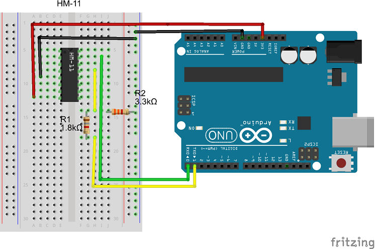
Now you have to connect the HM-11/MyoBridge Module to your Arduino. You need to connect the following pins:
- VCC to the 3.3V output of your Arduino
- GND to the Ground (GND) of your Arduino
- TX to the RX pin of your Arduino (this example uses the hardware serial, SoftwareSerial with other pins should work as well)
- RX via a voltage divider to the TX pin of your Arduino. The voltage divider protects the HM-11 from the 5V of the Arduino.
The hardware setup should look like this (The HM-11 IC is pinwise equivalent to the back side of the real module, with the antenna facing upwards):
