-
Notifications
You must be signed in to change notification settings - Fork 16
Soldering and assembling
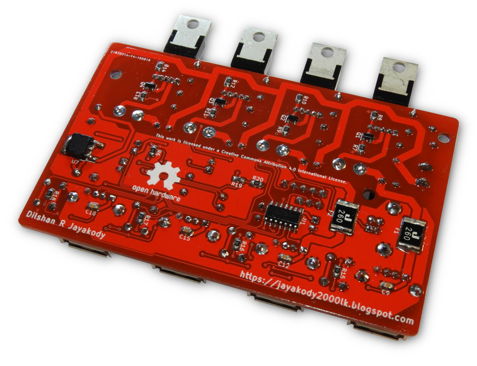
Following tools are necessary to assemble the USB hub:
- Soldering iron with tiny tip (or SMD rework station)
- Solder
- Solder flux
- A couple of tweezers
- Bench magnifying glass or microscope
- Nipper or cutting tool
During soldering try to solder small SMD components first. To overcome most of the problems we recommend to solder this board in the following order:
- Solder U1 (PIC16F630) IC first.
- C6
- J6, J7
After soldering the above components, connect the "PICKit 3" programmer to the J2 terminal and flash the U1 MCU. The programming procedure is described in the following section of the documentation.
Following the firmware upload, solder rest of the components to the PCB.

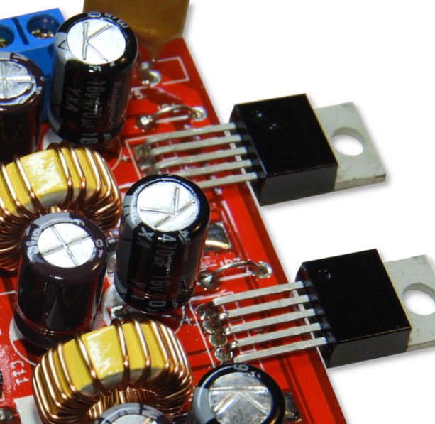
The power regulators of this PCB can fix in either horizontal or vertical positions. The regulator mounting layout depends on the size and style of the heatsink. If regulators are mounting in a horizontal position, then make sure to keep a minimum of 1mm - 1.5mm of spacing between PCB and regulator pins.
