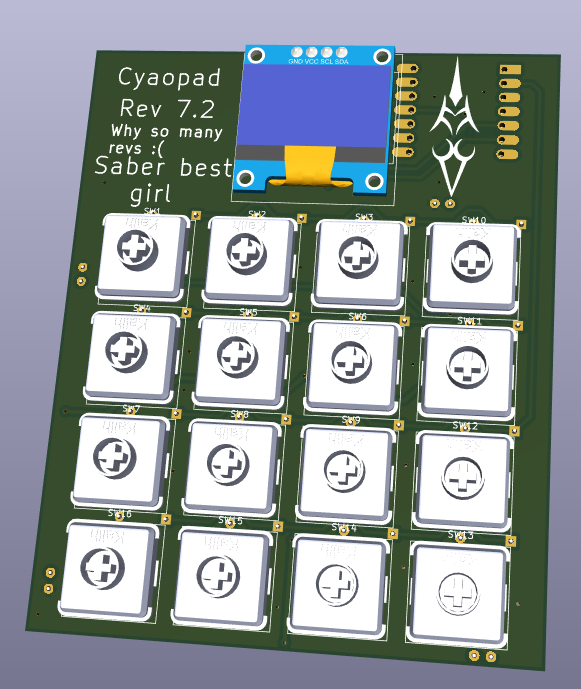
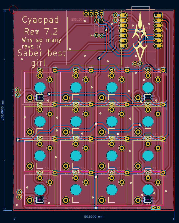
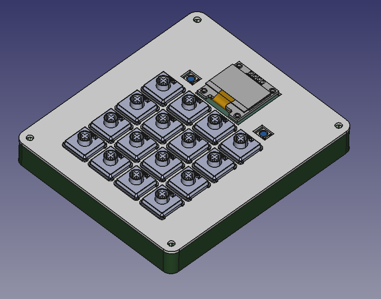
Hello! This is my first time designing a PCB and a CAD.
Designed using:
- KiCad - Made a ton of revisions
- OpenSCAD then FreeCAD (Fusion 360 doesn't work on my mac lol) Got like 400 constraints in my freecad project
- Python firmware
Making the pad was fun ^.^ but I was just too paranoid that something would go wrong and made 15+ revisions lol. Ended up learning how to use OpenSCAD and FreeCAD.
- 1 SEEEDUINO XIAO RP2040
- 16x Kailh Choc V2 switches
- 16x 1N4148 diodes
- 1x SSD1306 128x64O LED (5V VCC, 3.3V logic, I2C)
- 4x SK6812-MINI-E LED
- 2x 4.7k resistor
- 4x 0.1 uF capacitor (code 104, not obligatory but best have)
- 1x 1 uF capacitor (105 not obligatory)
- 4x same screws as orpheuspad and corresponding nuts
- 1kg of 99.99% gold please UwU
Interactive bom at PCB/production/ibom.html
.
├── CAD                                         # 3D Files
│   ├── case.FCStd                              # Case FreeCAD design file
│   └── case
│       └── case.stl                            # The stl for the case
├── PCB
│   ├── macropad.step                           # 3D Model of the board
│   ├── production                              # The output directory for production (Just send this folder to JLCPCB)
│   │   ├── Cyao_macropad_v7.6.zip              # Final gerbers
│   │   ├── *.{csv,ipc}                         # Misc files for JLCPCB
│   │   └── ibom.html                           # Interactive bom for PCBAlex <3
│   └── third_party                             # 3rd party libraries
│       ├── Kalih                               # The keys
│       ├── OPL_Kicad_Library                   # Seed footprint
│       ├── KiCad-SSD1306-128x64-master         # LCD
│       └── Seeeduino-xiao-rp2040-KiCAD-Library # Seed schema
└── firmware                                    # Directory of my own firmware
    ├── adafruit-circuitpython-seeeduino_xiao_rp2040-en_US-9.1.4.uf2 # Circuitpython firmware
    ├── main.py                                 # Main firmware
    ├── boot.py                                 # Boot options (empty)
    └── kmk                                     # kmk firmware
NOTE: I will need a 0.96” SSD1306 OLED screen that accepts 5V with 3.3V logic
The resistors are allso probably optional - but suggested by reddit


